
History / Motivation
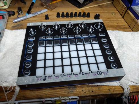
I got a the Circuit by Novation back in Fall of 2018. I was blown away by how simple and flexible the UI was, both for sequencing internal sounds, and as a MIDI note-controller for external gear.
Then, suddenly, it started glitching, at the pads.
It seemed fine if I held it ant an angle, but placing it on flat surfaces made it spazz out Then, about a year, the unit’s pads started falling into glitch-fits, as if I was tickling all over the pads
… as seen in this other person’s video:
Initial “lemonade” ?
Then, wanting to salvage this clever-and-portable controller/synth, I contacted Novation.
They promptly responded that, since the unit was no longer under warrantee, that I’d have to ship it to them for diagnostics and repair.

SO…
- $32 to look,
- $65 an hour
- 2+ weeks turnaround
- alternative to buy a new model for $120…
…I decided to repair it myself:
To the BENCH !
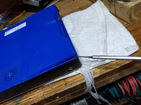
Then, after a few months of deliberation, I decided to open it up and fix it myself. I followed this very-well-phographed teardown by BoodyHole (who was just cleaning out beer)…
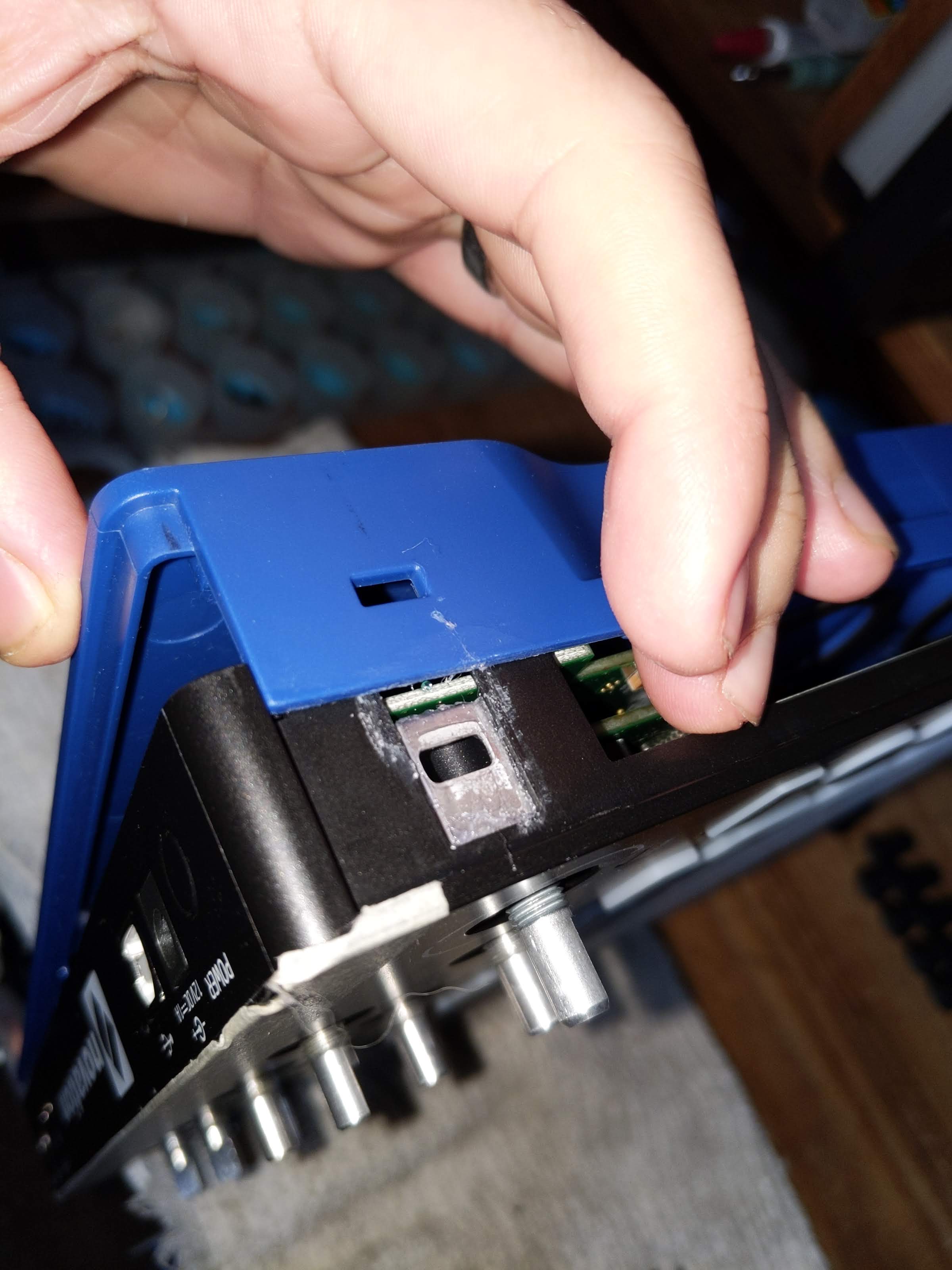
So, I pulled apart, and found the problem was a very simple fix !
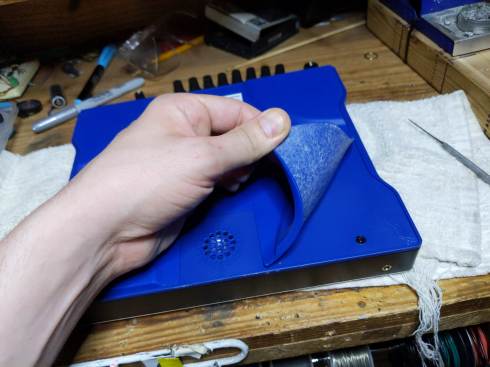


one standoff for the power/battery lines.
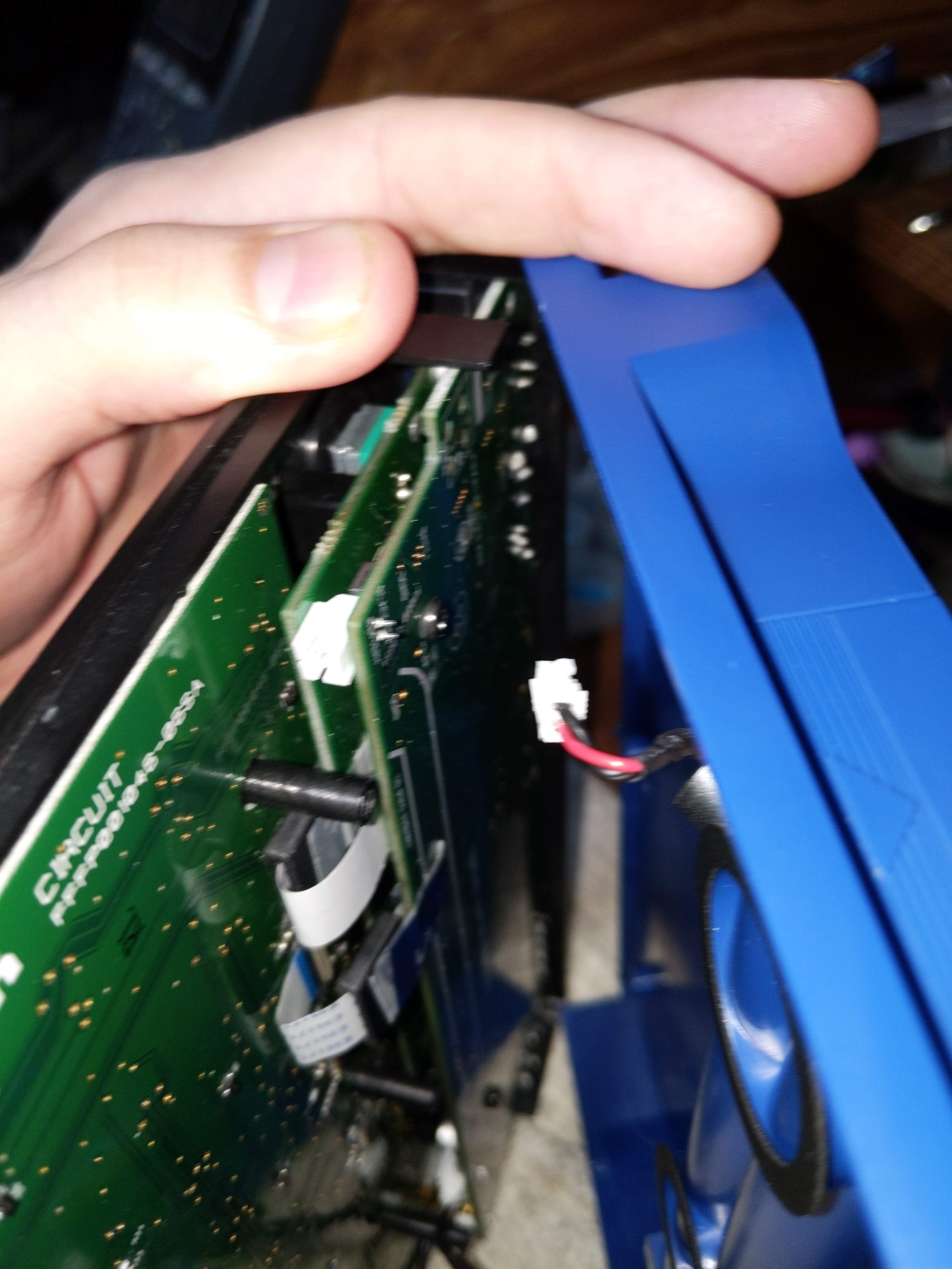

At this point, I noticed the two ribbon-cables between the two boards each had a magnetic shield, so I used some cellotape to keep each from being jerked around before proceeding…


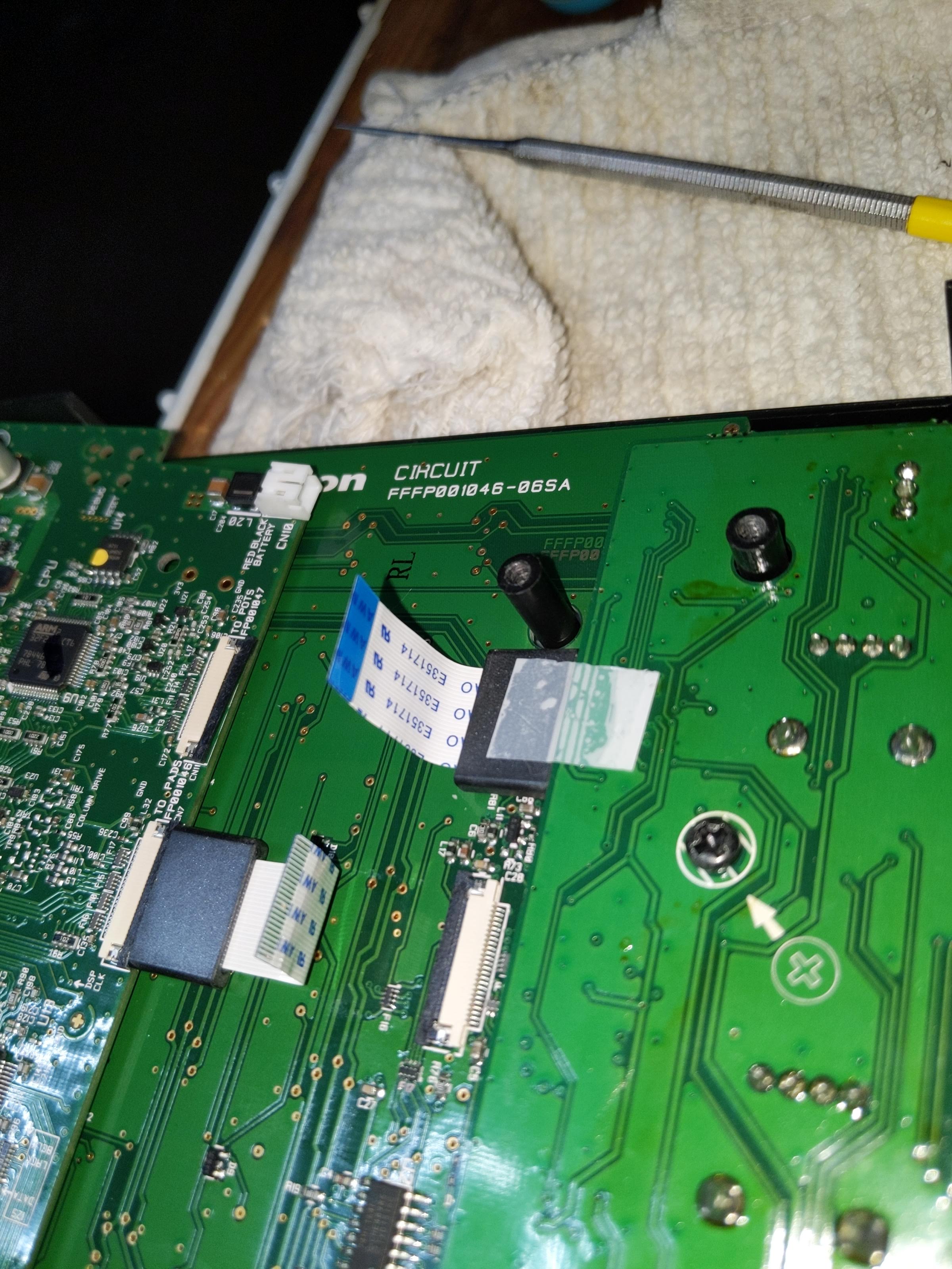

it was right HERE that I found the culprit (revealed below).


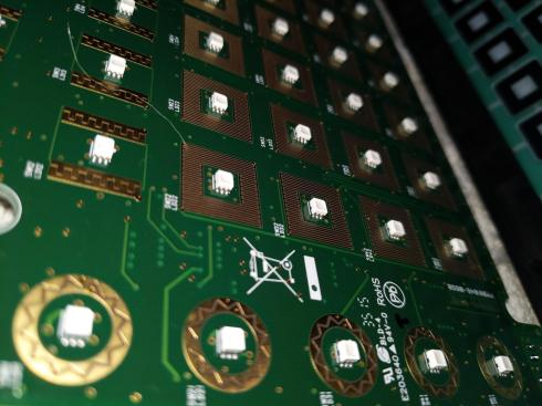
SideNote: SO HOW do these pads work ? (when they work).
At this point, I realized that the pads of the Circuit work quite differently than most other drum machines I’ve pulled apart. Most others have simple membrane switches for detective IF a button has been pushed, along with a piezo impact-sensor to catch how hard unit was hit. These are analyzed together to assign velocity to the last-hit-pad.
However, on the Novation circuit, there are no piezos.
I pulled a multimeter to check the rings.


Each pad pushes it’s semiconductive ring on a the square bloom of copper tracing.
I couldn’t find a (traditional shaped) piezo in the unit, so I guess the unit might be detective not only IF/when these rings mate, but how forcefully.
The unit might be scanning the (relative) conductance or voltage-division off these pads continually, acting as continuous force-sensing resistor assemblies. This would allows the control we already see from these pads:
- hit-events to be detected by looking for sudden changes per pad.
- key-holding action, where you can hold a pad like a keyboard key for indefinite sustain (something NOT regularly possible on piezo-equipped drum machine interfaces).
With this, I wonder if such a pad-design could support after-touch…even poly-phonic.
anyhow…
…but WHAT WENT WRONG !
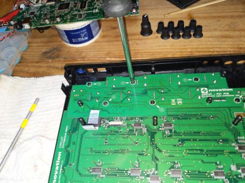
As mentioned above, when pulling up the PCB for the MacroKnobs, I heard a metal part fall to the desk.

This little slug of metal had been rattling around between the knob board and the pad board, likely shoring the traces that handle scanning/status of the pads (hence the “storm” of input”).
That metal tab is the anchor for the Kensington Lock slot, a feature that allows you to bike-lock your music gear to the retail/studio environment of your choice at the hazard of forcfully ripping the body to remove it.

The metal anchor fit neatly int the little slot, but was not glued in, so it not only feel inward to the calamity hear, but it could get moved/lost lost whenever someone hazards to open their circuit.
To fix this, I decided to super-glue the metal tab into place before re-assembling. If you EVER consider doing this yourself, be VERY careful to glue the metal to the “top” (black, pad-sided) chassis, and not the “bottom” (blue, rubber-backed) chassis.
NOT here like this…
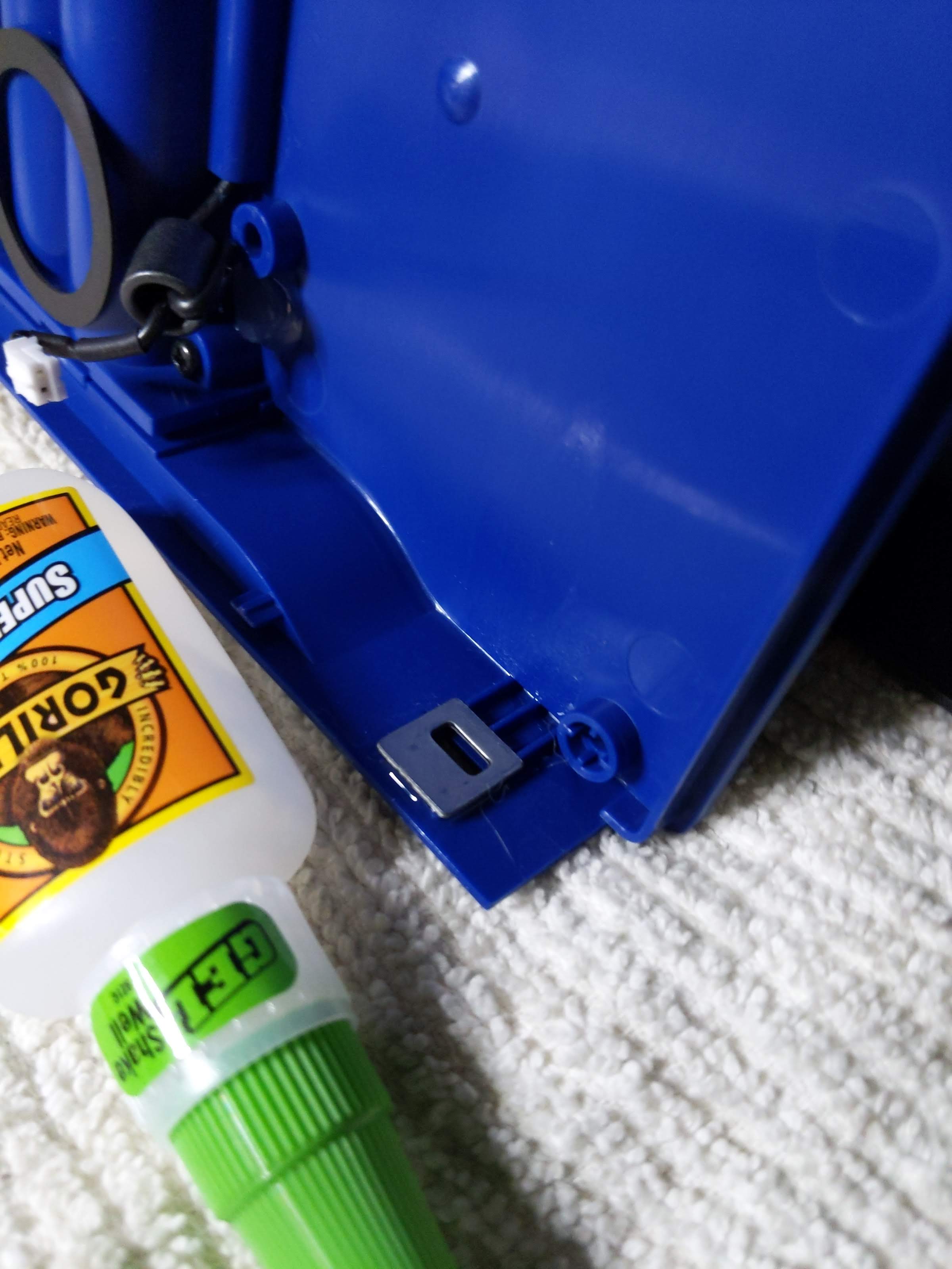
…but HERE, like THIS:
Man, removing my mistkenly-applied glue lead to considerable time wasted, but still avoiding the potential tragedy of sealing my Circuit shut… gotta think ahead, and consider what’ll happen when you put it back together.
Aftermath, afterthoughts…
After getting the unit re-assembled, it worked fine, and hasn’t glitched since (fingers crossed).
Having a second-life of functionality (and a new appreciation for the robust key-action) of my Novation Circuit has got me exploring this thing as a MIDI-keyboard-for-drummer… even looking into how I might store and play chords with and without the sequencer.
Bottom line…
Instead of paying Novation
- $80+ to service my unit
- OR
- $120 for a new unit…
I spent 2 hours, 1 beer, and no money to fix it myself. I’d hope that, if Novation finds that “pad-glitch-ing” units consistently show up with their loose Kensington anchors loose, they should offer a special repair-rebate program… and spend the money to glue down such loose metal parts in future editions.
If you’ve got a Novation Circuit with glitching pads, let me know. I’ll be happy to fix it for or with you.

Hey, I have a novation circuit. It had glitching pads just the same way you showed in your video two years back. It was in warranty so I got it fixed for free but a few time back this problem occurred again and on top of that it is dead now like it won’t even switch on so that I sample those glitching sounds lol. Please help me dude.
Thanks
Hey there Shubhang.
Sorry to hear about your dead circuit.
Can you email me at
thepatrickrichardson@gmail.com
with some more specific details/timeline of your experience with your circuit.
Also, fill me in on where you are located.
I’m in Philadelphia, PA.
If I have more information, I can figure out if/how I can help you.
Hey Shubang
Sorry for the delay.
I’ve been getting my repair-bench back in order.
Please email me at thepatrickrichardson@gmail.com, and we can make arrangements for a repair/service job.
hey Patrick–Great job! I found your post after mine just started doing this today. Given the fix, I wondered if maybe just some shaking / light hitting of the unit would clear up the issue (temporarily at least!) and so far it has. I’m assuming whatever metal piece is now in a benign corner of the unit. Thanks again for the diagnosis; If I get the energy will have to open it up and fix more permanently. Kevin
Hey Kevin. I would NEVER settle for letting a piece of conductive metal rattle freely around inside, as it may move to short out something more serious (like around the power supply). Let me know if you want help opening it up.
I bought a mint Circuit third-party and it has developed a substantial rattle. 😦
No problems with the pads hey but I take it to work w me every day. Fuck.
Where are you based ?
If you’re in the Philadelphia area, I could take a look at it, or I could walk you through it remotely.
It looks like I’ll have to become intimately acquainted with your teardown. That being said I haven’t contacted support yet.
Interesting.
If the item is out of warrantee, and you’d like me to look at it, email me.
cheers,
P.
It feels more like the PCB flopping around inside, but in your teardown there are screw(s) that look like they would prevent that. I can take some video of the “rattle” later tonight. It’s deeper, more of a “shuffling” sound lol. Definitely not the Kensington tab thingy.
Hey Tristsan
Sorry for the delay in response.
Can we switch this over to email:
send email and/or video to thepatrickrichardson@gmail.com
Hey! That’s my video up there! Glad it’s getting some use. I took it to send to Novation support. My unit was replaced under warranty, and at the time there were no tear-downs available for it. I’m a total fix-it guy, so if it hadn’t been under warranty, I would have opened it up.
Hey Chromatest ! Great to have you come by !
Yes it is your video, and thanks for sharing/relating your problem for me to find and work on.
Since my finding your video and blogging a tear-down, i’ve gotten TONS of inquiry about other people with the same problem. Might be my biggest source of blog-inquiry (so far).
I’ve even done some repairs for people who sent their units to me (voiding their warrantee, of course).
I’m surprised Novation have remained quiet on this matter.
Thanks for this. Your post encouraged me to take it apart. Even though i did NOT have the luck of finding a loose metal piece as the culprit, the pads worked after cleaning them with alcohol. Hooray! Again, thanks.
Thank you so much for this walk-through. I was having the same issue with my circuit. Pads glitching. I let it sit for months and eventually tried to send it in but because I bought it used they were going to charge me for repairs. They said it could cost up to the price of a brand new one. So I followed your tutorial and it only took me about 45 mins. Same thing, the Kensington anchor was loose. Glued it back in and its good as new. I can’t thank you enough! Such a blessing. Thanks!
Good on you, J4TUN.
Thanks for reading.
Eew blessings gross
IT burns
Hello, thank you very much for your guide to open it, my circuit has been failing for some months and as the colleague says above with a small blow it was fixed temporarily … luckily that solution worked for me when the problem presented itself to me in full presentation about it scenario … I will encourage myself to open it to repair it definitively … I will comment on my results.
greetings from Chile
Cool
Do it yourself, fix it yourself.
Keep us posted.
Many thanks for this blog post Patrick. I was having issues with an OG Circuit I recently bought second hand. I opened it up and there it was – the very same metal tab from the Kensington Lock slot rattling around inside. I just took it out – I don’t expect I’ll need to use the lock slot so didn’t see the need to glue it back in place. Fingers crossed that’s solved my issues – all seems well so far.
I think this is a design flaw. I think maybe it’s just gravity holding the metal tab in its slot. So when the Circuit is turned upside down – as might well happen in the post say – the tab gets loose inside the Circuit and is entirely likely to short out all kinds of circuitry. Not sure if Novation have resolved this with newer Circuit models.
Cheers!
Hugh
Roger that Hugh… join the cause an help us out on the UK side !
If anyone is having similar issues in the UK and would like me to take a look at their Circuit feel free to drop me a line by replying here
Hi,
My Circuit was glitching for two years and was sleeping somewhere in the attic. Thanks to your tutorial, I got it repaired in less than five minutes. You’re my hero! Thank you so much !
You’re very welcome !
Hello, a potentiometer has broken. How do you change them and where do you buy the potentiometer?
SYNTAUR has some good stock.
https://syntaur.com/keyboard.php?keyboard=1818&brand=Novation&model=Circuit
eMail me if you’d like me to do the soldering for the part for you.
Hey, just thought I’d add another comment saying thanks for this detailed teardown and solution. I work at a library makerspace and our Circuit had been glitching out for months, with a few moments of working properly. I followed your guide and it was exactly the same issue you had! It was bothering me for ages and Novation had nothing to say about it when I pinged them on Instagram.
Great to hear.
I’m a strong supporter of Right to Repair, as it’s part of
“Reduce, Re-use, REPAIR, Re-purpose, Recycle”
Where is your maker space ? I did a bit of MakerSpace work in Philadelphia.
You might be interested in the sonicware smpltrek
Thanks.
I meant the Comment on the MicroSampler for another thread.
I checked it out, but it looks almost “too small”….and I’m not sure I’d dig the small screen.
I’ll definitely check it out to see how “hands on, eyes off” it is.
Thanks for documenting the disassembly so well! Just thought I should mention that, on my Circuit, the problem has never been the Kensington slot. The metal shim has never been loose inside the case, and I’ve never had to glue it in place. Instead, the problem in my experience (and the experience of many on the official Circuit Facebook group) seems to be the ribbon cables connecting the pads to the processing board. Re-seating these often solves the problem for a while, but eventually I find they come loose again. I’ve actually drilled holes in the rubber foot for my Circuit to make this job easier, as it’s happened probably 5-6 times since I bought it used in 2019.
Bottom line: if you follow this guide and the Kensington slot shim isn’t loose, and/or gluing it in place doesn’t work, try re-seating the ribbon cables.
Excellent observation, science, and engineering my friend BC1009.
Awesome move to give your Novation Circuit an acess vent (“undercarriage sun-roof”) to fix the problem without having to pull panels.
Baller customization. Check out my custom work on my Korg MicroSampler !
Just wanted to say thanks and yes my circuit had the exact same problem with the loose Kensington lock. Once removed, it worked perfectly. Looks like a design flaw indeed!
Glad to hear hear and help.
Spread the word !
Thanks for the instructions and great photos for this fix! Using tape on the ferro things is a great idea. There are a couple of little details missing which might help, (but they are fairly obvious) “First remove the knobs AND nuts and washers”. Also there is a 3rd connector as well as the two ribbons. I forgot to reconnect this 3rd connector when I put it back together and the result was no sound – everything else working fine, just no sound. Mine was responding poorly to button pushes and the cure was a complete clean of the pads and contacts with isopropyl alcohol. The Kensington lock thing came loose in the case, but only as I opened the case and I left it out when re-assembling.
Hey Steve.
Sorry if I left a few steps out. I was actually writing most of this article as I was doing the tear-down.
Thanks for the comment/note. I’ll add your notes.
Hey! I dont know if you or someone out there has the same problem as i do. Some of my pads are hardened. The pads usually are already a bit stiff and that did not change, but some of the pads are requiring me to hit it real hard for it to work. While others work just fine and i can just press it for it to respond.
i’m thinking about opening it and putting some glue in the inside part of the pads and them glueing something really thin between the pads and the black rings so it would be easier for it to be pushed into the pcb part and detect the pressing of the pad.
I will do that by this weekend and can comeback here later to tell my results.
Really dont know what to expect, but logically i think it should work….. but what do i know, for sure nothing about eletronics, i’m but a humble psychologist Xd
hey Ped. Sorry for late response.
Sorry to hear your pads are getting fit-fully stiff. Unfortunately, the pads make electromechanical contact w/ the circuit boards, and this conduction is how they sense intensity/pressure.
So, putting “inserts” would interrupt this mechanism.
If you pads require harder hitting, it’s possible that natural wear-and-tear may be rubbing said electrical contact down, so it can’t sense “full force” right now.
If you’d like me to take a look inside your Circuit, I may not be able to fix it, but I could do some quick diagnostics to see if the breakdown is happening on the pad side (easy/cheap replacement) or the circuit board side (potentially more costly service/replacement).
Let me know if/how I can help.
Cheers
Patrick !
Also… Psych was my college major.
I only got into electronics coming out of college.
What kind of psychology do you study/practice/focus ?
You could try to carefully clean the contact surfaces with some 90+ percent rubbing alcohol and a q-tip. Don’t press super hard.
YES !…
Cleaning the contacts SHOULD help, but be careful w/ high-grade rubbing alcohol, given there are so many soft-plastics and small-scale electronics inside the unit.
I’d suggest using Contact Cleaner first…and see if that helps.
Also, the electrical contact is just a pad of resistive material, so you don’t want to rub it off w/ harsh chemicals or excessive force.
Cheers !
yes… whatever you use, don’t press hard, just “buff” !