Installing 8-jack remote (foot)switch patch bay on Korg MicroSampler

Motivation:

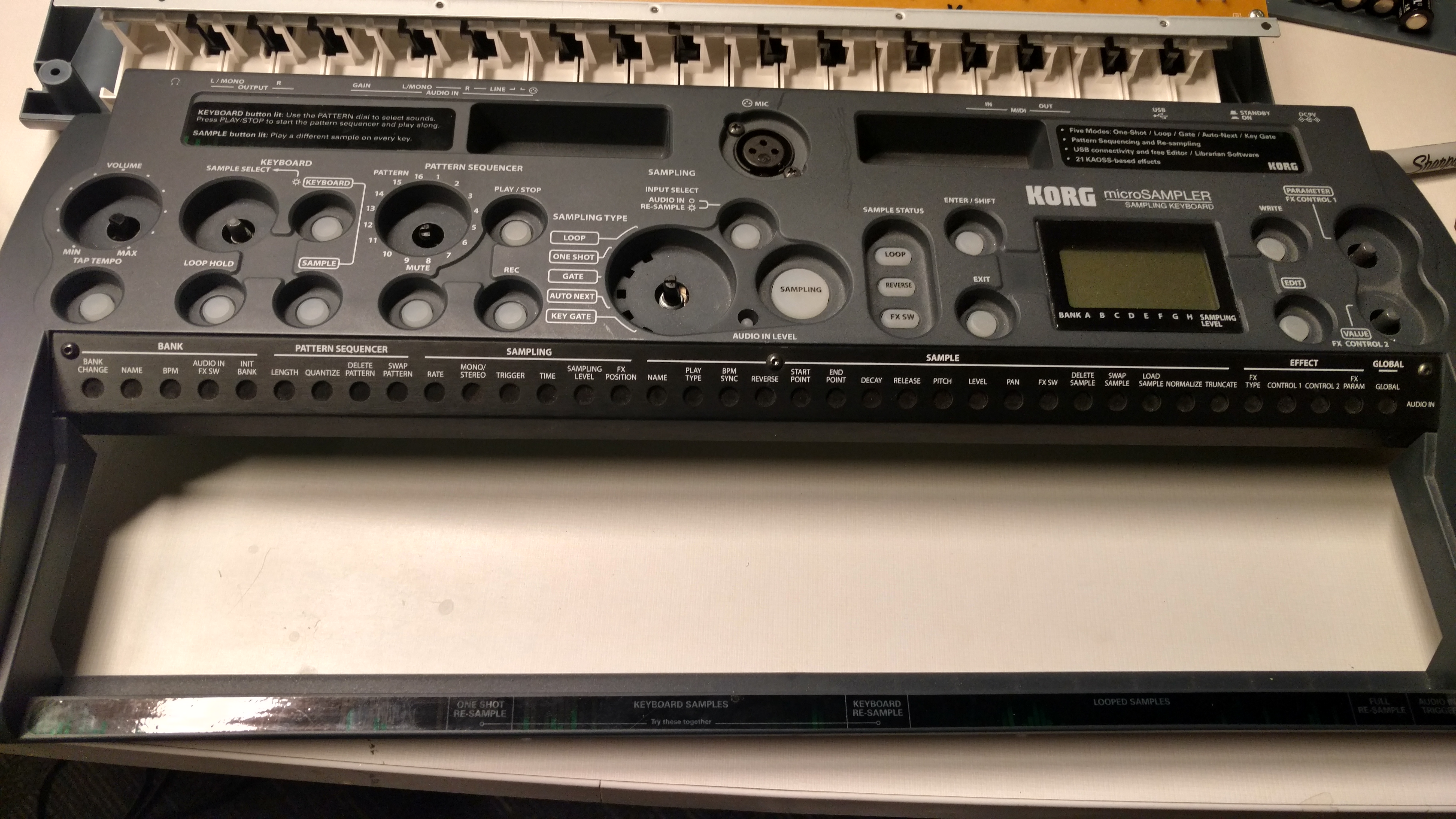
A little over a week ago, I compiled my thoughts on my Korg MS1 microsampler into a “review”… which concluded with some consideration of hacking into it’s little plastic body to overcome some of the limitations of it’s “unevenly graceful” User Interfacing.

After studying this thread by Orchards in the Korg Forums about soldering wires to remote-short the contacts of the onboard switches right at the internal printed circuit board (PCB), I decided it was time to buy a new, smaller solder tip and take it…

To the Bench !

Here’s a photo-document of

Getting in:

As always, hacking and modifying any electronic gear is a warrantee-voiding, do-at-your-own-risk affair. Be careful, plan ahead, and work slowly.

Doing something like this tends to go smoothly with a proper and prepared start. Working our way INTO the device can be the scary part, so let’s break that down;

00-prep
Ready for surgery !
01-open-back
remove screws from back panel. All screws are the same at this point, so keep them safe.
02-open-back
The back panel hosts the battery pack, connected to a small(er) circuit board.
03-remove-daughers
The main challenge of working here is the interconnection between the keybed board (bottom, tan) the I/O board (top right), the motherboard (top left), and the User Interface board (deeper).
04-remove-keybed
We’re after the UI board, and to solder switch-offs from the solder-points that the knobs/buttons/etc on they UI board use.
05-careful-standoffs-label
Make sure to note (or mark) which ribbon cable or stand-off mates with what, so you can avoid confusion or dysfunction upon re-assembly.
06-pull-knobs
remove the Keyed, and the knobs from the front allows us to pull out the UI board.
07-expose-main-pcb
Flip the freed UI board, and we see the gloriously simple and well-labeled contacts of each button. It’s important to plan here. I spent a lot of time flipping this back-and-forth to set up wires through the right  for each contact-pad.


Wiring the “short-off”s and re-assembly

The essence of this hack is electronically dead-simple; the onboard buttons make a short (electrical connection) between two sensor points. We’re just wiring those points to onboard jacks to connect rugged, external switches of our choice.

However, given how the UI board in question is the front-most in the stack, and we’ve gone in from the back (through the daughters), it’s key keep our wires long enough to reach the mounting of the jacks, and keep their identity straight.

08-g-pad and gage.gif
Here wee see the metal contacts for a switch (in this case, the Tap Tempo) lead to traces with holes that connect to the solder pads that we’ll wire through. I found 28 gage wire (when twisted, not tinned) would fit through the holes.
09-standoff-pin-carelss
DRAT ! … be VERY careful when soldering. I got sloppy and burned one of the plastic stand-offs that connects a wire-bundle between motherboard and daughterboard. This required me to take finish the surgery at home (where I had the right tools to fix this error). Don’t think you can sneak your iron in and work in pockets; pull each panel out to work on it freely.


10-internal-lengths
I used two colors of wire, blue (to the inner/top of each swtich) and grey to the outer (which proved to be grounded). It helped keep me organized, and leaving enough slack for any short-off wire to reach past the full length of the body assured things wouldn’t come up short on re-assembly.


11-hanging-grafts
Once I got all the short-offs soldered, I hung and twisted them into tidy pairs.


13-comb-and-lay
Then taped each twisted pair to the body to thread them around and off the PCB of the UI board to make it re-assembly easier.
14-label-contacts-before-reassembly
Before flipping the labeled-front of the motherboard back in, I labeled the business end of each pair.
12-drill-open-panel
While UI board was still out, I drilled pilot holes for the “Jills” to mount each remote-short. Others seem to have gone into the back-panel (over the “Korg” logo), but I wanted to do eight, so I went for the keyboard’s spacious left side-panel.
15-organize-into-re-assembly
Then comes the tedium of keeping things untangled while putting it back together.
16-tangle-discovered
During re-assmbly,  I noticed one of the pairs hooked under the shaft stem for a front-panel knob…so I had to back up and re-furrow that.
17-daughters-down
Be careful to keep your wires from tangling while putting the mother- and sister-boards back in place.
18-bag-left-overs
Had to stop to take the project home to address the plastic stand-off connector I burnt and figure out what kind of jills I’d be connecting these wires to. I bagged the still-out screws, and put those into another pouch-bag with the labeled ends to ensure nothing got scrambled in transit.


Installing the CORRECT “jack”s (…JILLS)

Now on to the final stage; soldering these leads to whatever I’ll plug the switched into.

While we’re on the subject; why are the panel-mounted female receptacles (which a MALE connector plugs INTO) called the “Jack”.

In the interest of keeping this hetero-normative metaphor straight, I vote we start calling that part the “Jill”…

Time to see what fits:

19-phone-jack-is-too-big
after pulling out some 1/4” phone-stye connectors (“JILLs”) I found they were too deep to fit into the gap between the PCB and housing/panel
20-rcas-fit
Good news: standard RCA “jill”s were shallow enough across the array….


21-rca-thread-needle
Bad news: where (most) Phone-connectors reach through inside and tighten with nut on outside, these RCA panel-mount connectors thread IN from the outside, must thread through a ground-tab collar, and tighten with an INTERNAL washer and nut…

This took a LOT of patience and clever clamp work, as I had to solder the parts before screwing them together. That required

  1. soldering grey ground wire to the collar tab.
  2. threading blue lead wire through the tension nut, then ground collar and then the panel hole.
  3. soldering blue sensor wire to the tab on the Jill
  4. backing assembly back into hole
  5. priming the now-soldered wires with a few anti-clockwise twists of slack so they wouldn’t tighten or rip when
  6. holding the nut still while twisting the (fragile) RCA jill-head to screw tight.

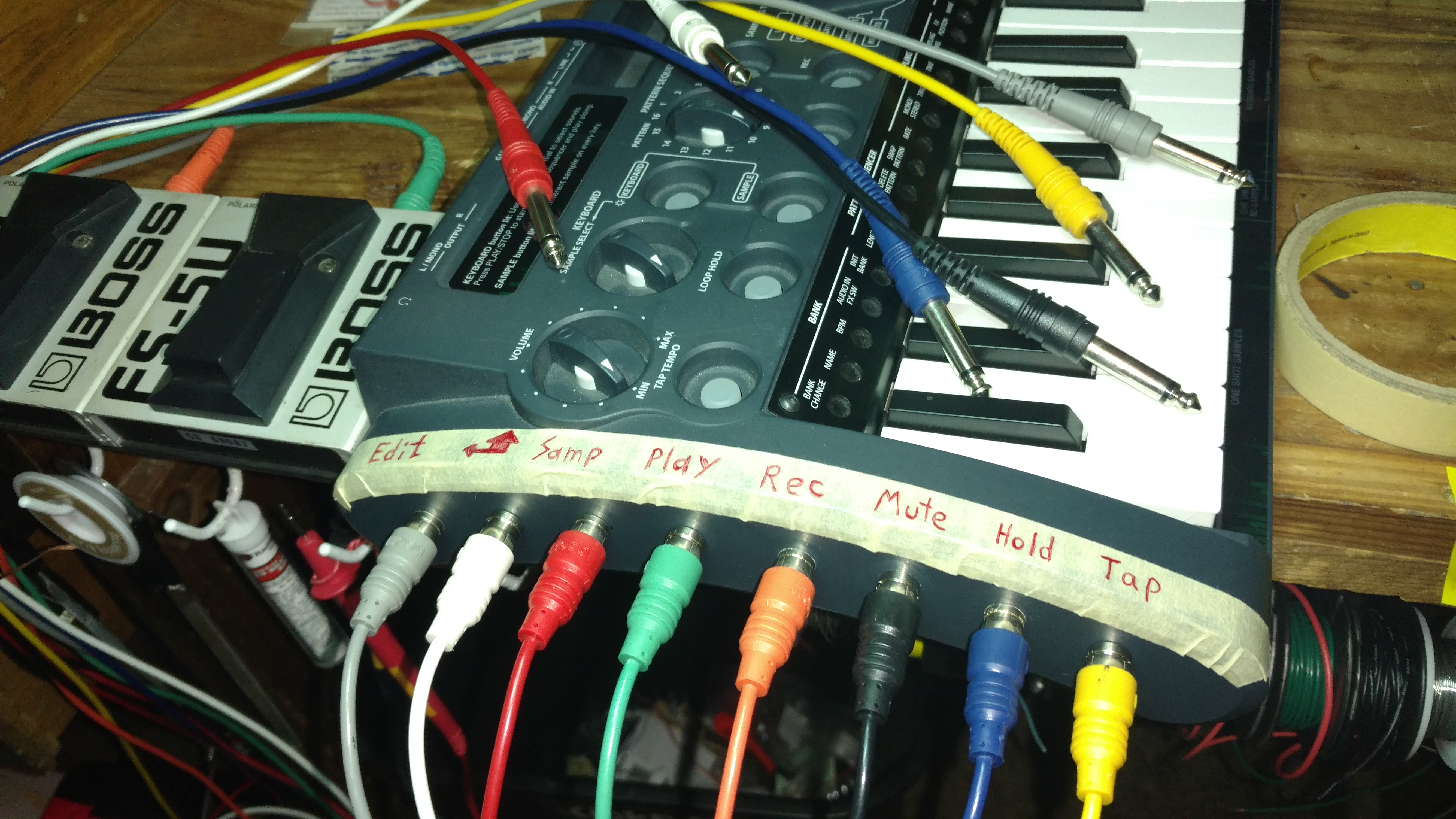
This was the part of the work with the most sweating and swearing, but eventually, I got all 8 jills mounted.

22-rcas-all-in
View of finished work of all 8 RCA jills wired and mounted
23-all-done
Was happy to find an Hosa loom of  8 mono 1/4”-phone-to-RCA connectors.


The above photo shows all 8 connections (right to left)

  1. Tap: to change the Bank tempo by foot (while drumming, etc) to so the Pattern Sequencer, the Sync’ed loops and/or timed effects can keep up with me for a change.
  2. Hold: to latch on looping samples, or sustain Keyboard chords. Press/releasing this without (un)latching single keys will un-hold all. Very handy to do one-handed.
  3. Mute: prevent triggering of select slots by Pattern Sequencer. Creates breakdowns within a pattern.
  4. Play/Stop: to start-stop the pattern sequencer.
  5. Rec: to enter Pattern recording, or while recording, jump between “write” and “rehearse” mode.
  6. Sample: manual start/stop of sample recording. This was the button remote-switched by Orchards on the Korg Forums.
  7. Shift/Enter: (using a hybrid of their typewriter graphics), used to confirm changes, or get various short-cuts from the other buttons I’ve foot-ed…
    1. Shift + Hold: hold all loops; will set HOLD for all samples set to Loop “on”
    2. Shift + Mute: mute all sequence; doesn’t stop Held keys.
    3. Shift + Play/stop: re-zero sequence; resets and plays sequence from start.
    4. Shift + rec: undo/redo; for previous cycle of recording activity
  8. Edit: allow jumping into various menus by the keyboards hot-keys. This way I can keep the right hand on the Page and Value knobs, page around with foot-and-left-hand.


After (re)testing all 8 jacks with some momentary-closure pedals…wow I just have to figure out how I’m going to organize 8 foot switches, especially considering the abundance of shift-sensitive actions.

Screen Shot 2017-02-28 at 4.21.47 PM.png
…from the Korg MS-1 user manual; table of all Shift-button-combination-shortcuts.


Makes me consider drilling some remote jills for the FX Switch, the Exit button, and perhaps others.

Let me know what you think about this hack and report in the Comments section below !


One thought on “Installing 8-jack remote (foot)switch patch bay on Korg MicroSampler

Leave a Reply

Fill in your details below or click an icon to log in:

WordPress.com Logo

You are commenting using your WordPress.com account. Log Out /  Change )

Facebook photo

You are commenting using your Facebook account. Log Out /  Change )

Connecting to %s